The BUSSide
Welcome to using the BUSSide!
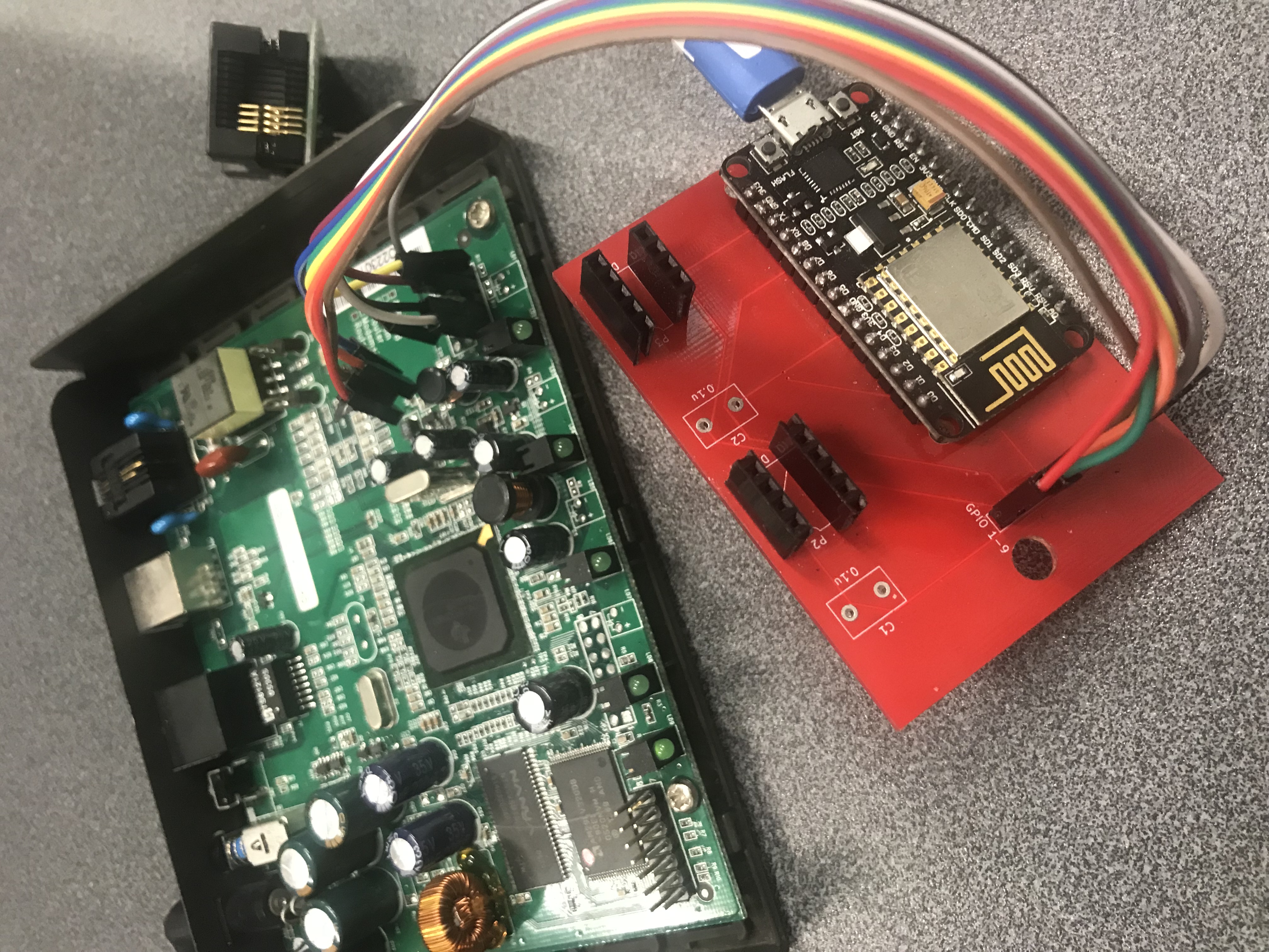
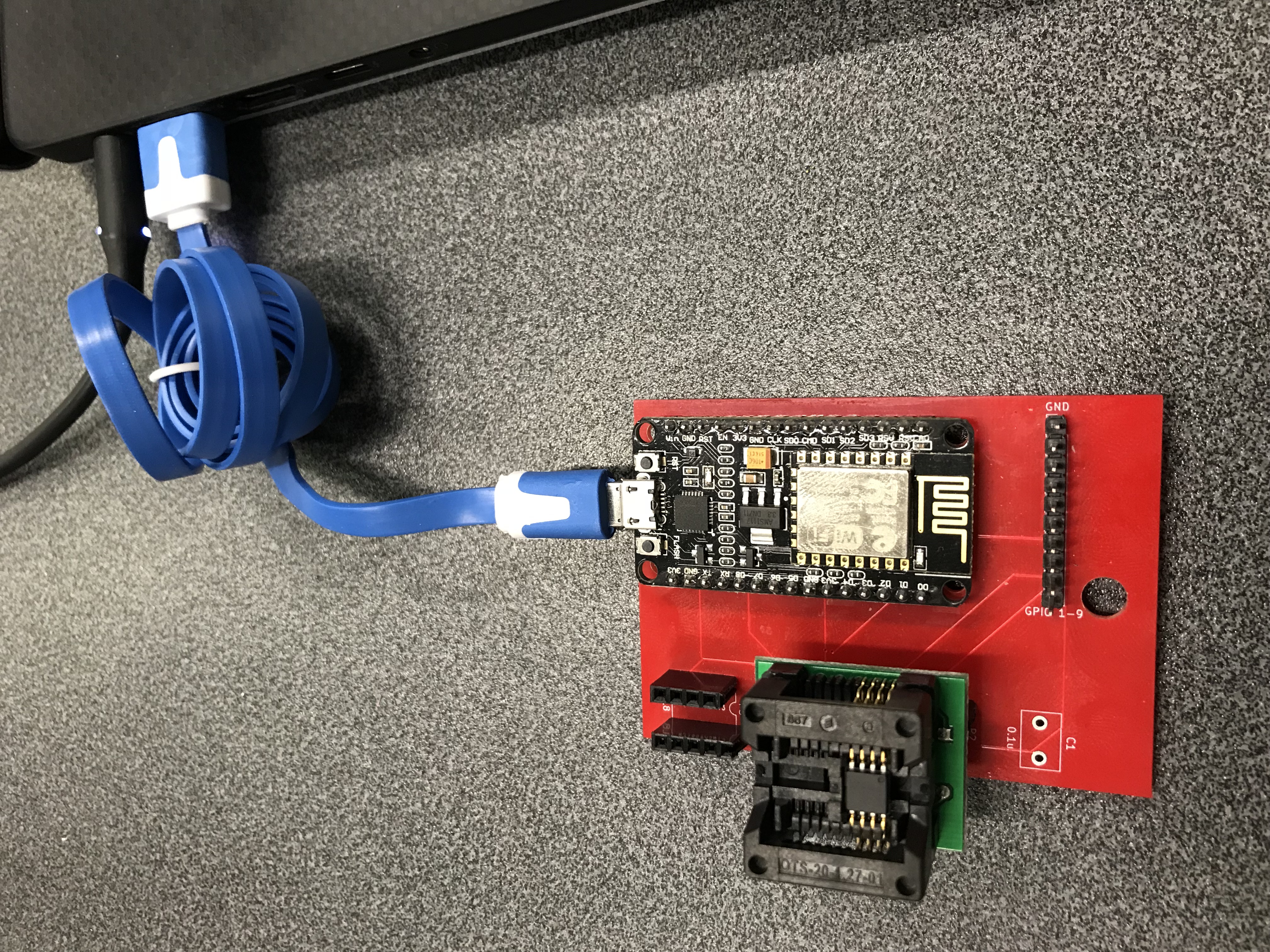
How to assemble
This document has images for the BUSSide v1. v1 has been replaced with the current v2 model. The software is the same between v1 and v2, but the physical layout of the board has changed in v2. Take note when using it and make sure your pinout is correct!
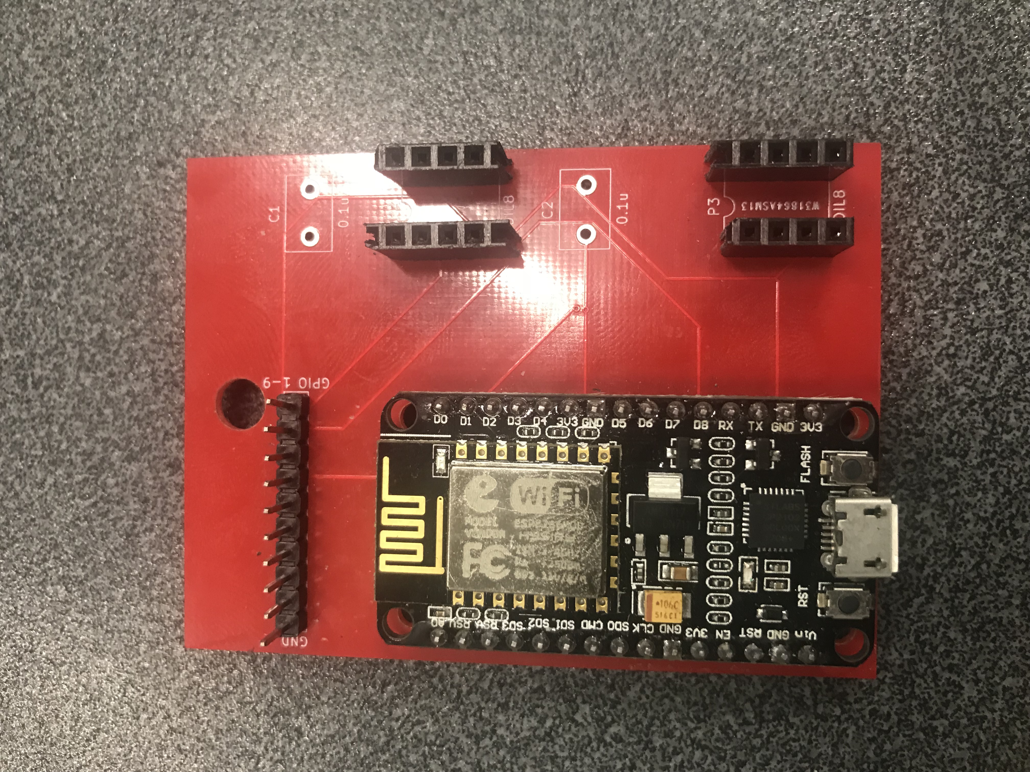
- 4 x 4-pin female header strips
- 1 x 10-pin male header strip
- 1 x NodeMCU v2
- 1 x 10-rainbow cable
- USB cable
2 Capacitors are optional and not necessary, nor given.
How to install the software
Download the software from https://github.com/BSidesCbr/BUSSide.
- Install the Arduino IDE
- Install the NodeMCU board into the IDE
- Set the board to NodeMCU 1.0
- Set the speed to 160MHz (via the IDE in the Tools dropdown)
- Install https://github.com/plerup/espsoftwareserial into the Arduino libraries
- Compile and upload the program
The Arduino IDE can be downloaded via https://www.arduino.cc/en/Main/Software
To install the NodeMCU v1.0 board into the Arduino IDE do the following:
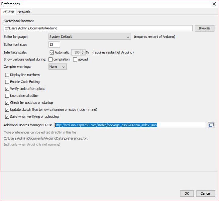
Go into the IDE under File -> Preferences and in “Additional Boards Manager URLs” add “http://arduino.esp8266.com/stable/package_esp8266com_index.json”
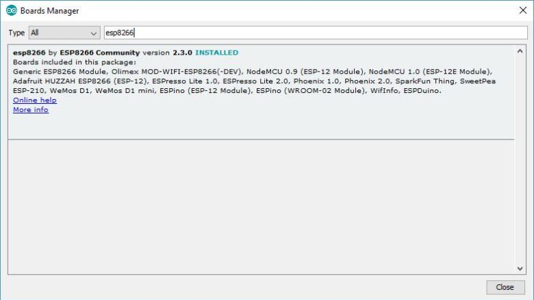
Now go to Tools -> Boards -> Boards Manager. Search for esp8266 and install the package.
Now go to Tools -> Boards and select the NodeMCU 1.0
Don’t forget to go into Tools and set the NodeMCU speed to 160MHz.
Installing the desktop client controller software
The desktop client controller software must run on Linux. This is because the Windows serial driver for the NodeMCU is not well supported. The easiest way to do this is fire up a Linux VM and use USB passthrough in your virtualization software for the serial device.
The controller software is written in Python. To use it, go into the working directory and run ./busside.py
# ./busside.py /dev/ttyUSB0
+++ Connecting to the BUSSide
+++ Initiating comms
+++ Sending echo command
+++ OK
+++
+++ Welcome to the BUSSide
+++ By Dr Silvio Cesare of InfoSect
+++
+++ The BUSSide accepts the following commands
+++
+++ > spi send <cmd1> ....
+++ > spi flash readID
+++ > spi flash dump <size> <outfile>
+++ > i2c discover pinout
+++ > i2c discover slaves <sdaPin> <sclPin>
+++ > i2c flash dump <sdaPin> <sclPin> <slaveAddress> <size> <outfile>
+++ > jtag discover pinout
+++ > uart passthrough auto
+++ > uart discover rx
+++ > uart discover tx <rx_gpio> <baudrate>
+++ > uart passthrough <rx_gpio> <tx_gpio> <baudrate>
+++ > help
+++ > quit
+++
+++
>
How to use
The BUSSide can be used in a number of different ways. The following list shows the functions of the BUSSide.
UART
- Detecting UART
- UART passthrough
JTAG
- Detecting JTAG
SPI
- Dumping SPI Flash
- Reading ID of SPI Flash Device
I2C
- Detecting I2C
- I2C Slave Discovery
- Dumping I2C Flash
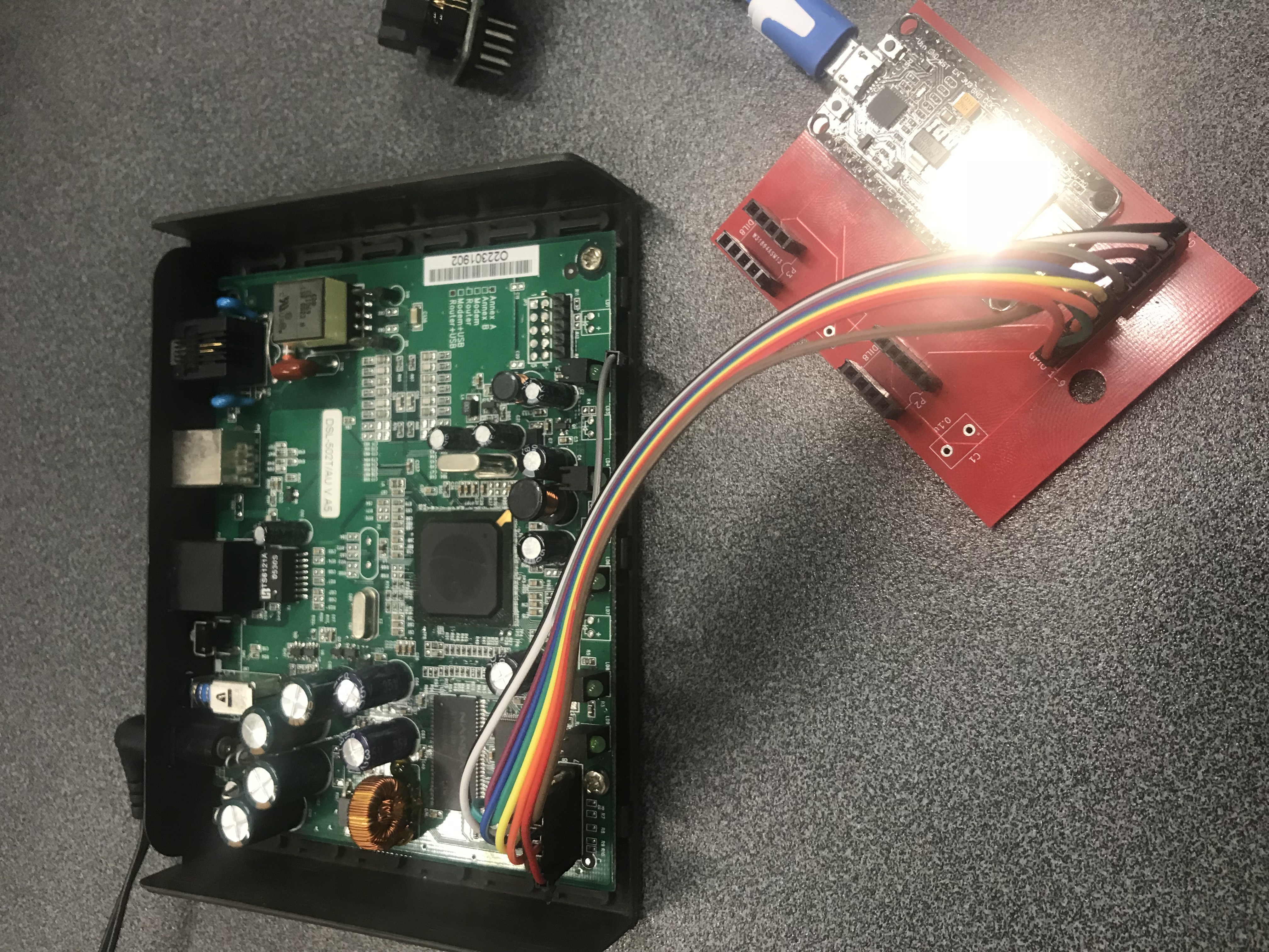
You plug in your Busside via USB. Remember, use Linux and USB passthrough. You will need to connect the BUSSide to the device that you’re testing. More on this is presented later for connecting ground and the GPIO pins. Lets assume you’ve connected the BUSSide to the device.
The BUSSide is ready to take commands.
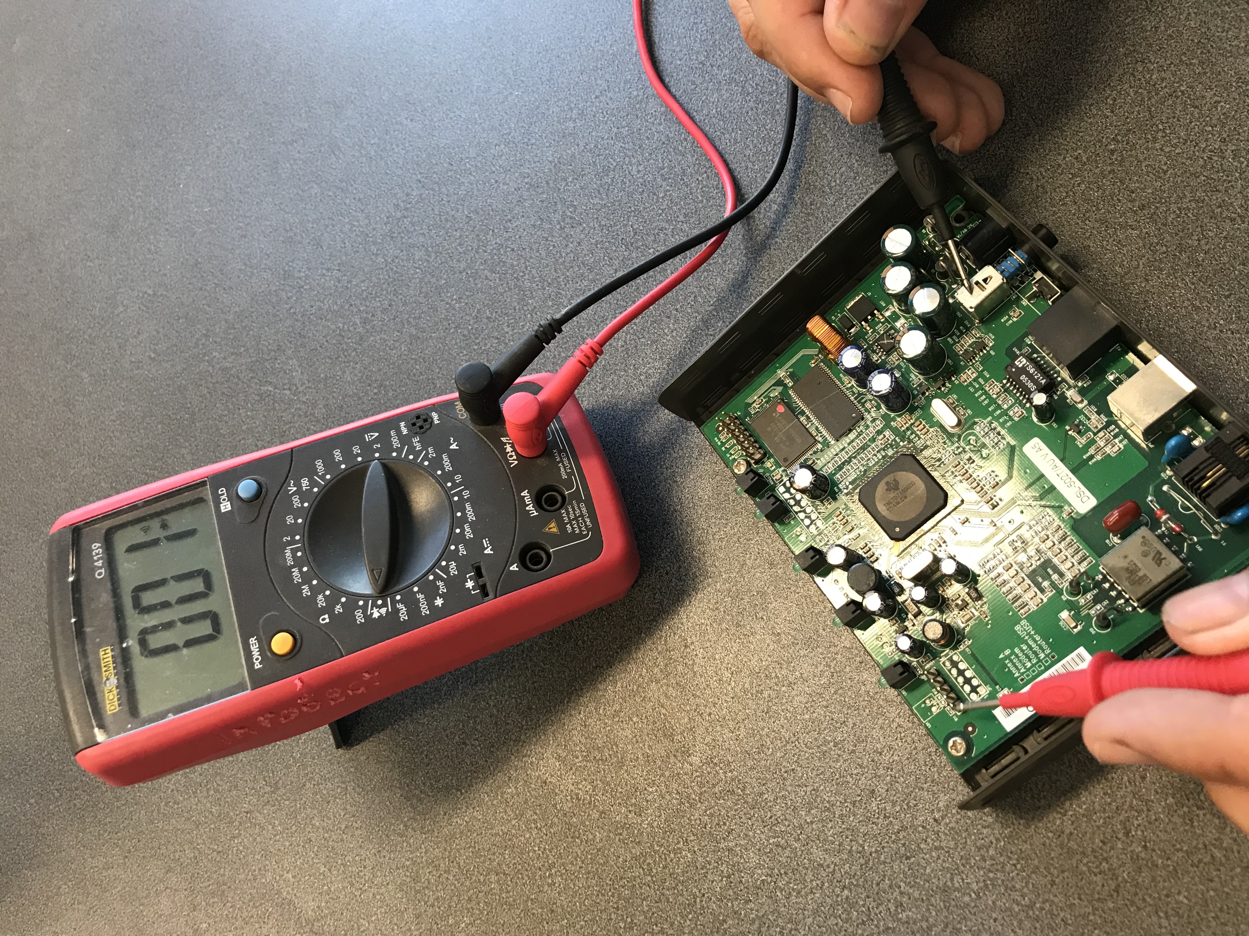
Connecting the ground pin
The first thing you want to do to use the BUSSide on a device is to identify the ground pin on the headers you are interrogating. It’s quite easy to determine ground pins. You take your multimeter and put it into the continuity test mode. Now you connect one probe to the pin you are testing and the other probe to somewhere on the ground plane. The ground plane often includes things like metal shielding internal to the device. If that doesn’t work, you might need to connect it to ground on the DC socket. If your multimeter beeps, you have identified a ground pin. If you can’t detect any ground pins, you might not have found the ground plane. Try any other shielding if it is available.
Now you need to connect the ground pin on the device to the BUSSide.
Connecting the GPIO pins
Now you want to connect the other pins to the BUSSide. If you want to detect UART or determine if test points are JTAG pins, then connect them. It doesn’t matter what order you connect the pins, but if the BUSSide detects a pinout, you need to recogonise which GPIO pin on the BUSSide is connected to which pin on the device.
Note that GPIO 1-9 on the BUSSide corresponds to D0-D8 when using the controller. Also note that the pin immediately adjacent too the ground pin on the BUSSide corresponds to D0.
1 Line to get a UART Shell
If only 1 UART is connected, then you can try to get a shell immediately with the ‘uart passthrough auto’ command.
> uart passthrough auto
+++ Connecting to the BUSSide
+++ Initiating comms
+++ Sending UART discovery rx command
+++ GPIO 1 has 0 signal changes
+++ GPIO 2 has 2 signal changes
+++ GPIO 3 has 0 signal changes
+++ GPIO 4 has 188 signal changes
+++ UART FOUND
+++ DATABITS: 8
+++ STOPBITS: 1
+++ PARITY: NONE
+++ BAUDRATE: 38400
+++ GPIO 5 has 0 signal changes
+++ GPIO 6 has 0 signal changes
+++ GPIO 7 has 0 signal changes
+++ GPIO 8 has 0 signal changes
+++ GPIO 9 has 0 signal changes
+++ Sleeping for 60 seconds to get an idle UART.
+++ Connecting to the BUSSide
+++ Initiating comms
+++ Sending UART discovery tx command
--- Warning. Retransmiting Attempt #1
+++ Connecting to the BUSSide
+++ Initiating comms
+++ Sending UART discovery tx command
+++ FOUND UART TX on GPIO 3
+++ SUCCESS
+++ Connecting to the BUSSide
+++ Initiating comms
+++ Entering passthrough mode

Starting pid 33, console /dev/tts/0: '/bin/sh'


BusyBox v0.61.pre (2007.11.02-05:10+0000) Built-in shell (ash)
Enter 'help' for a list of built-in commands.

#
Detecting UART RX
The BUSSide can detect the transmit (tx) pin of a UART connection if it is present and automatically determine the line settings including the baudrate, the number of data and stop bits, and the parity, if any, that is used.
To perform the detection, the UART must be transmitting data. The easiest way to make this happen is to boot the device. During bootup, it is common for boot messages to be sent over serial console via UART.
Here is an example of detecting UART in a DLINK DSL-502T ADSL router:
> uart discover rx
+++ Connecting to the BUSSide
+++ Initiating comms
+++ Sending UART discovery command
+++ GPIO 1 has 0 signal changes
+++ GPIO 2 has 16 signal changes
+++ GPIO 3 has 34394 signal changes
+++ UART FOUND
+++ DATABITS: 8
+++ STOPBITS: 1
+++ PARITY: NONE
+++ BAUDRATE: 38400
+++ GPIO 4 has 0 signal changes
+++ GPIO 5 has 0 signal changes
+++ GPIO 6 has 0 signal changes
+++ GPIO 7 has 0 signal changes
+++ GPIO 8 has 0 signal changes
+++ GPIO 9 has 0 signal changes
>
The UART connection above was detected.
Detecting UART TX
Lets continue from above. We’ll wait until the ADSL router becomes idle before detecting the TX pin. If we don’t wait until the UART is idle, we might not detect it.
We note the RX pin was found GPIO 3 and the baudrate was detected as 38400.
Note that this feature does not work with GPIO 1. So avoid that pin. Likewise, don’t use it in UART passthrough mode.
> uart discover tx 3 38400
+++ Connecting to the BUSSide
+++ Initiating comms
+++ Sending UART discovery tx command
+++ FOUND UART TX on GPIO 6
+++ SUCCESS
>
UART passthrough
Once you have detect the tx and rx pins and the line settings for UART, you can do UART passthrough.
We note that RX is on GPIO 3, TX is on GPIO 6, and the baudrate is 38400.
> uart passthrough 3 6 38400
+++ Connecting to the BUSSide
+++ Initiating comms
+++ Sending UART passthrough command
+++ Entering passthrough mode

Starting pid 33, console /dev/tts/0: '/bin/sh'


BusyBox v0.61.pre (2007.11.02-05:10+0000) Built-in shell (ash)
Enter 'help' for a list of built-in commands.

# ls
bin      etc      proc     usr      var.tar
dev      lib      sbin     var
#
Detecting JTAG
The BUSSide can detect JTAG pinouts if JTAG is present. This is similar to what the JTagulator does.
> jtag discover pinout
+++ Connecting to the BUSSide
+++ Initiating comms
+++ Sending jtag pinout discovery command
+++ 1 JTAG FOUND
+++ TCK 6
+++ TMS 4
+++ TDI 3
+++ TDO 1
+++ NTRST 2
+++ SUCCESS
>
If you have issues with detecting the JTAG pinout, then try reorganizing the order of the GPIOs. This sometimes helps.
Reading ID of SPI Flash
We can read the chip ID.
> spi flash readID
+++ Connecting to the BUSSide
+++ Initiating comms
+++ Sending SPI read ID command
+++ SPI ID ef4017
+++ SUCCESS
>
And using our own pinout
> spi flash readID 9 6 8 7
+++ Connecting to the BUSSide
+++ Initiating comms
+++ Sending SPI read ID command
+++ SPI ID ef4017
+++ SUCCESS

>
Dumping SPI
If you have identified a SPI serial flash chip on a board, you can dump the flash contents using the BUSSide. You need to know how big the flash memory is and to do this normally you will take the part number off the chip and look up its datasheet. In actual fact, the flash size is not contained in a viewable configuration and serial flash is designed to rollover back to the beginning if you dump a size bigger than it holds.
There are multiple ways of physically interfacing with an SPI chip. You can desolder the chip and use the supplied SOP8/SOIC8 to DIP adapters. The top DIP adapter on the BUSSide is the SPI interface. Below it is the I2C interface. Another option is using something like a Pomona test clip and attaching the jumpers to the BUSSide. In this scenario, you don’t need to desolder the chip.
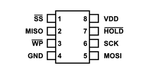
The important pins are MOSI, MISO, SCK, and GND. HOLD is also required for serial flash.
The BUSSide dumps SPI serial flash much faster than the Bus Pirate v3.6. The Bus Pirate would normally take 15-20 minutes to dump 8M of flash. The BUSSide can do it in 3 and a half minutes.
You also need to specify an output file. In the command below, we’re dumping 100,00 bytes into the file 1.bin.
> spi flash dump 100000 1.bin
+++ Connecting to the BUSSide
+++ Initiating comms
+++ Dumping SPI
+++ SUCCESS
>
A bigger example is dumping 8M from the flash of an ADSL router.
> spi flash dump 8388608 1.bin
+++ Connecting to the BUSSide
+++ Initiating comms
+++ Dumping SPI
--- Warning. Retransmiting Attempt #1
--- Warning. Retransmiting Attempt #1
--- Warning. Retransmiting Attempt #1
+++ SUCCESS
Note that 3 retransmissions were made. This is indicating error correction took place due to noise in the serial connection. This is perfectly normal and expected in large dumps.
Lets take it 1 step further and run binwalk on the dump.
root@kali:~/Desktop# binwalk -e 1.bin

DECIMAL       HEXADECIMAL     DESCRIPTION
--------------------------------------------------------------------------------
14772         0x39B4          LZMA compressed data, properties: 0x6D, dictionary size: 4194304 bytes, uncompressed size: 144236 bytes
65536         0x10000         Broadcom 96345 firmware header, header size: 256, firmware version: "8", board id: "6328ang", ~CRC32 header checksum: 0xF8EFE9AD, ~CRC32 data checksum: 0x40BC74E0
65792         0x10100         Squashfs filesystem, little endian, non-standard signature, version 4.0, compression:gzip, size: 6103538 bytes, 711 inodes, blocksize: 1048576 bytes, created: 2012-01-11 07:31:58
6172940       0x5E310C        LZMA compressed data, properties: 0x6D, dictionary size: 4194304 bytes, uncompressed size: 3673532 bytes

root@kali:~/Desktop# cd _1.bin.extracted/
root@kali:~/Desktop/_1.bin.extracted# ls
'['                             mtab
 0                              mtd0
 1                              mtd1
 10100.squashfs                 mtdblock0
 2.6.30                         mtdblock1
 39B4                           mtdblock2
 39B4.7z                        mtdblock3
 3g-mngr                        mtdblock4
 5E310C                         mtdblock5
 5E310C.7z                      mtdblock6
 ac97                           mtdblock7
 adsl                           multicast.html
 adslcfgadv.html                multinatadd.html
 adslcfgc.html                  multinat.html
 adslcfg.html                   mxp
 adslcfgtone.html               nas
 adslctl                        nas4not
 adsldd.ko                      natcfg2.html
 adsl_phy.bin                   NB14WN3_banner_v2.jpg
 advanced_1.xml                 NB14WN3_banner_v2_tianchong.jpg
 advanced_2.xml                 nc
 advanced.xml                   net
 algcfg.html                    netcomm_log.jpg
 arl                            netctl
 arpview.html                   netfilter
 atmdelerr.html                 nf_conntrack_ftp.ko
 b28n.js                        nf_conntrack_h323.ko
 backupsettings.html            nf_conntrack_ipsec.ko
 bcm                            nf_conntrack_ipv4.ko
 bcm43112_map.bin               nf_conntrack_ipv6.ko
 bcm4312_map.bin                nf_conntrack_irc.ko

...
You can see we pulled out a lot of data. You can now try mounting the squash filesystem.
Discovering SPI pinout
> spi discover pinout
+++ Connecting to the BUSSide
+++ Initiating comms
+++ Sending spi discover pinout command
+++ FOUND 1 SPI interfaces
+++ SPI interface FOUND
+++ SPI CS at GPIO 9
+++ SPI CLK at GPIO 6
+++ SPI MOSI at GPIO 8
+++ SPI MISO at GPIO 7
+++ SUCCESS
Sending SPI Commands
Using default pinout
> spi send default 0x9f 0x00 0x00 0x00
+++ Connecting to the BUSSide
+++ Initiating comms
+++ Sending SPI command
+++ SPI Response: ff
+++ SPI Response: ef
+++ SPI Response: 40
+++ SPI Response: 17
+++ SUCCESS

>
Using GPIOs:
> spi send 9 6 8 7 0x9f 0x00 0x00 0x00
+++ Connecting to the BUSSide
+++ Initiating comms
+++ Sending SPI command
+++ SPI Response: 00
+++ SPI Response: ef
+++ SPI Response: 40
+++ SPI Response: 17
+++ SUCCESS

>
SPI Fuzzing and command enumeration
> spi fuzz 9 6 8 7
+++ Connecting to the BUSSide
+++ Initiating comms
+++ Sending spi fuzz command
+++ FOUND 7 SPI commands
+++ SPI command FOUND
+++ SPI command 03
+++ SPI v1 00
+++ SPI v2 00
+++ SPI v3 00
+++ SPI v4 10
+++ SPI v5 00
+++ SPI command FOUND
+++ SPI command 05
+++ SPI v1 3c
+++ SPI v2 3c
+++ SPI v3 3c
+++ SPI v4 3c
+++ SPI v5 00
+++ SPI command FOUND
+++ SPI command 90
+++ SPI v1 00
+++ SPI v2 00
+++ SPI v3 00
+++ SPI v4 ef
+++ SPI v5 00
+++ SPI command FOUND
+++ SPI command 92
+++ SPI v1 00
+++ SPI v2 00
+++ SPI v3 f1
+++ SPI v4 f1
+++ SPI v5 00
+++ SPI command FOUND
+++ SPI command 9f
+++ SPI v1 ef
+++ SPI v2 40
+++ SPI v3 17
+++ SPI v4 00
+++ SPI v5 00
+++ SPI command FOUND
+++ SPI command ab
+++ SPI v1 00
+++ SPI v2 00
+++ SPI v3 00
+++ SPI v4 16
+++ SPI v5 00
+++ SPI command FOUND
+++ SPI command bb
+++ SPI v1 00
+++ SPI v2 00
+++ SPI v3 00
+++ SPI v4 17
+++ SPI v5 00
+++ SUCCESS

>
Discovering I2C Pinouts
Attach the ground pin, and connect the GPIOS. You can’t use GPIO 1.
> i2c discover pinout
+++ Connecting to the BUSSide
+++ Initiating comms
+++ Sending i2c discover pinout command
+++ FOUND 1 I2C interfaces
+++ I2C interface FOUND
+++ I2C SDA at GPIO 9
+++ I2C SCL at GPIO 2
+++ SUCCESS
Discovering the I2C slave address
Like the SPI interface, you can interface with I2C on the BUSSide using the DIP adapter or using jumpers. The pinout is as follows.
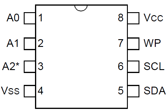
The requires pins are SDA (data), SCL (clock), and VSS (ground). You don’t have to supply power if you are attaching to a powered on device via jumpers.
Here I’ve attached the BUSSide to a digital answering machine which exposes an I2C EEPROM.
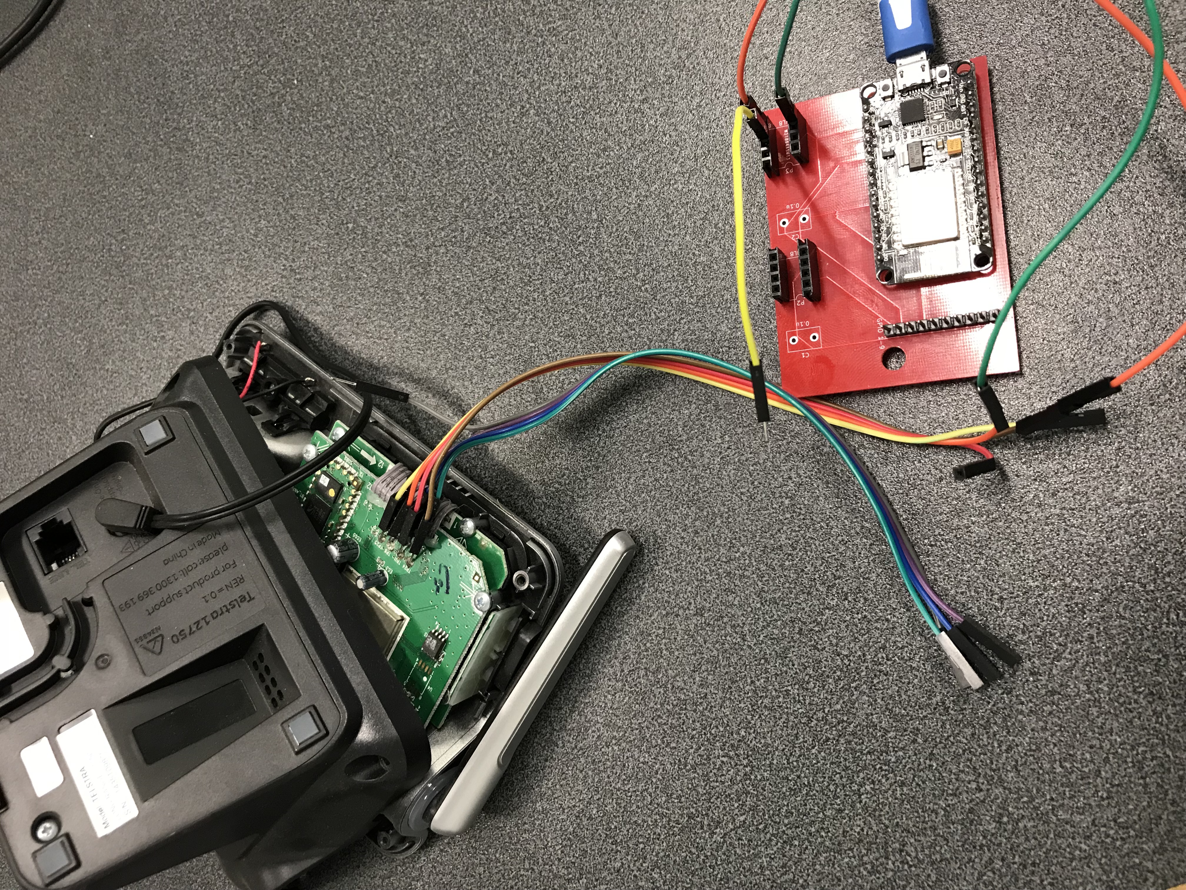
Each I2C device has an ‘address’. GPIO 9 is SDA and GPIO 2 is SCL. To discover this address, we use the following:
> i2c discover slaves 9 2
+++ Connecting to the BUSSide
+++ Initiating comms
+++ Sending i2c slave discovery command
+++ 1 I2C slave addresses
+++ I2C slave address FOUND at 80
+++ SUCCESS

>
Dumping I2C
Now that we have pinout and the I2C slave address, we can dump the EEPROM. In the following example, we are dumping the size of the eeprom which is 64k to the output file 1.bin. Note also, the argument after the slave address and before the dump size, is the size in bytes of the address. Many I2C eeproms use a size of 2, but some might use 1.
> i2c flash dump 9 2 80 2 65536 1.bin
+++ Connecting to the BUSSide
+++ Initiating comms
+++ Dumping I2C
--- Warning. Retransmiting Attempt #1
--- Warning. Retransmiting Attempt #1
--- Warning. Retransmiting Attempt #1
--- Warning. Retransmiting Attempt #1
--- Warning. Retransmiting Attempt #1
--- Warning. Retransmiting Attempt #1
--- Warning. Retransmiting Attempt #1
+++ SUCCESS
>
Flashing I2C
Here we are writing 256 bytes from 1.bin to I2C on GPIOS 9 and 2, with slave address 80, and address length 1.
> i2c flash write 9 2 80 1 256 1.bin
Limitations
The BUSSide does not like to be interrupted during an operation. Try to let each operation complete before doing something else. Don’t hit ctrl^c to interrupt a client controller.
Troubleshooting
Although generally unlikely, if the client scripts start reporting timeouts in connecting to the BUSSide, just unplug the BUSSide and plug it back in. Almost all problems can be resolved by turning it off and on again.
If you have issues with detecting the JTAG pinout, then try reorganizing the order of the GPIOs. This sometimes helps.