Hardware CTF 1
This is the Hardware CTF 1.
Register your name/handle with InfoSect CTF to track your progress and compare yourself to others http://ctf.infosectcbr.com.au:8000.
Solve each level to get the flag. Once you have the flag, enter it into the CTF to get your points.
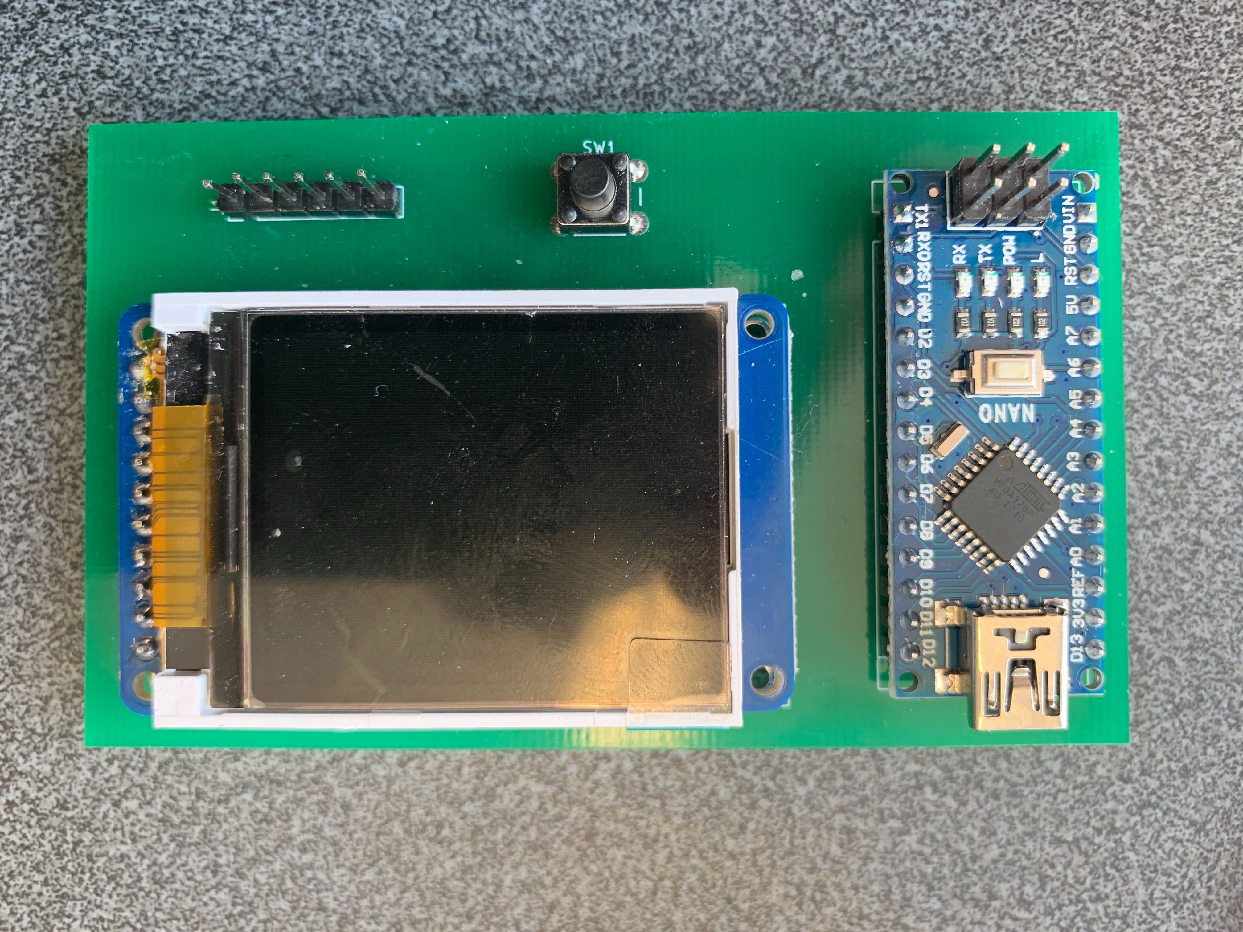
How to assemble
- 1.8”Adafruit TFT display and header pins
- Arduino Nano
- Header pin strip
- Button
Solder the screen first. Make sure not to solder into the mounting holes. Double check this more than once!
Solder the Arduino Nano next. Make sure you put it in the right way around. This part is tricky and the fit is tight. Keep going, you can do it! Feel free to use a little bit of force.
Solder the header pins and the button.
How to install the software
Attach the badge via USB to your computer. If you are using a VM, be sure to do USB passthrough:
Grab the firmware blob from github and flash it under a Linux terminal:
$ git clone https://github.com/infosectcbr/InfoSect-Hardware-CTF-1
$ cd InfoSect-Hardware-CTF-1
$ sudo ./flash_hwctf1.sh /dev/ttyUSB0
If your badge is on /dev/ttyUSB1 or another port, use that instead.
The BUSSide
You will need an up to date version of the BUSSide firmware (from 16-12-2019) for the I2C challenges. Please check out https://github.com/infosectcbr/BUSSide.
Level -
Look at the firmware blob. Can you find an embedded flag?
Level 0
If you can assemble and flash the badge, this will be enough to get the flag!
Level 1
You will need to interface via UART. The pinout and line settings are given. Use a serial-uart bridge. We recommend and have tested with https://www.jaycar.com.au/arduino-compatible-usb-to-serial-adaptor-module/p/XC4464.
To use the usb to serial adapter, connect TXD/TX, RXD/RX, and GND/Ground.
Open up minicom in a Linux terminal. Assuming the USB serial adapter is on /dev/ttyUSB0 use the following. If the adapter is on /dev/ttyUSB1 or elsewhere, use that instead.
$ sudo apt-get install minicom
$ sudo minicom -D /dev/ttyUSB0
Type ctrl-a, then ‘z’ on it’s own. This will enter you into the menu system.
Type ‘o’ which will enter you into the configuration. Scroll down to the serial port setup and hit enter.
Type ‘f’ to turn off software flow control. If you don’t do this, you will not be able to interface correctly.
Change the baud rate to the appropriate setting.
Exit out of the menu system.
Do you get readable text from your UART connection?
Level 2
You will need to determine the line settings for UART. Try brute forcing them perhaps?
The trick to knowing the baud rate, is to simply try each baud rate in turn and see if you get legible text.
Level 3
You will need to determine the pinout and line settings.
The trick to determining the pinout for UART is to find the TX and RX pins individually. Try different pins connected to RX/RXD on your usb serial adapter. If you see garbled text, you’re receiving transmissions from the device under test. Now you need to figure out the baud rate (if you got it wrong). Now you simply try to find TX/TXD by connecting it and hitting a few buttons or enter. Did you get a response?
Level 4
Same as level 3, but it’s harder. The Hardware CTF isn’t transmitting data so it’s harder to brute force. But if you type something and it correctly receives it, the CTF will respond.
Level 5
Use the BUSSide to dump the I2C EEPPROM. There is a video on how to do this with the BUSSide on a standard EEPROM via YouTube at https://www.youtube.com/watch?v=MWO07mJBgMM.
Level 6
Same as level 5 except you have to figure out the slave address of the I2C EEPROM.